
CHALLENGE 1 - introductory course
Install programming software
15 min


STEP 8
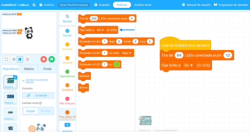
I defined the chosen digital PIN.
This PIN is the one we use to connect the LED Matrix to the Arduino.
STEP 8
I defined the chosen digital PIN.
This PIN is the one we use to connect the LED Matrix to the Arduino.

STEP 8
I defined the chosen digital PIN.
This PIN is the one we use to connect the LED Matrix to the Arduino.

STEP 8
=> Show Cursor
=> Wait 0.1 seconds
The wait is necessary for it to react after 0.1 seconds; if we don't wait, when we press it, the cursor will shoot out at an exaggerated speed and we won't be able to control it.

STEP 8
We create a new variable that we will call PreviousCursor
To the variable that we just created we assign the value that the cursor variable has at that moment in the program.

STEP 8
We put together a block to control the buttons.
Digital pin 3 (B1), when pressed it is activated (1). When it is not pressed then (0).
=> (Digital Pin 3)=1

STEP 8
When we press the top button, which is connected to PIN 3, we increase the cursor variable by 8 units, since we want to “Go Up”.
For example, if we are on LED 2 and we press the button to raise the cursor, LED 10 will turn on, therefore our cursor variable must increase by 8 units.


STEP 8
At this point we must create a new variable which we will call drawing, this variable will determine whether the LED on which we are standing should or should not stay on once we move the cursor
We add an if...then...else block to cover both cases of the drawing variable (it will only be equal to 0 or 1)

STEP 8
If the variable drawing is equal to 1, it refers to what we want to draw, that is, the LED on which we are standing must remain lit once we move our cursor.
To achieve this we must add a block to turn on LED and in the place referring to the number of LEDs to control we place our previous cursor variable, then we proceed to turn it on in a certain color, in our example it was decided to turn it on in white (255,255,255) but it could be done in any color

STEP 8
For the Sino part, which means that our variable drawing is equal to 0, we want the LED to be off once we move the cursor, so the previous action is repeated with the slight change that instead of assigning a color we leave it off (0,0,0)

STEP 8
We do the same with the next button that is connected to PIN 4
In this case we want that when pressing this button our cursor moves to the right, so we subtract -1

STEP 8
The digital PIN 5 will be responsible for determining whether we have to draw or not, that is, assigning the value 1 (Draw) or 0 (Do Not Draw) to the variable drawing.
To do this, the first thing we place is a If... then... but depending on the value of the mentioned button, assign one value or another

STEP 8
In our case, when the digital PIN 5 registers a 1 (when it is pressed), we want the variable drawing to be equal to 1 so that our program knows that we should draw that LED
To achieve this we must use the block that sets the value of the variables and in the drop-down menu we select the drawing variable and assign it the value 1

STEP 8
For the opposite case, when the button is not pressed (we are in the Else of the block) we repeat the same procedure of assigning a value to the variable drawing, but in this case we assign it the value 0, so that the program understands that this LED should not be drawn.

STEP 8
We do the same with the next button that is connected to PIN 6
In this case we want that when pressing this button our cursor moves to the left, so we add 1

STEP 8
When we pass LED 63 the counter will continue counting, so we have to tell it that when it reaches LED 63 it will return to 0.
The counter variable is not limited by the number of LEDs, we limit it that way for our purpose.
We added a block that allows us to say if it is greater than 63 then...
Cursor>63

STEP 8
When the condition created in the previous step is met, we have to decide what to do with the value of our cursor.
We set the Cursor to 0.
In this case we chose to return to zero when we pass LED 63 but it could be determined to start again at any other LED.

STEP 8
When we are on Pixel 0 and we want to move to the right, we would be subtracting 1, moving to the -1 LED which does not exist, therefore in that case the cursor should remain on LED 0.

STEP 7
Tell your Arduino which port it is connected to.
Tools/Port/*select_port*
You have to mention dev.Arduino Uno, dec/cu.usbserial or COM. If many appear, try until it lets us upload.

